Pulse composite Pulse to voltage converter translator adapter Simple voltage-to-pulse duration converter diagram pulse to voltage converter schematic
Pulse Transformer Schematic Diagram - Circuit Diagram
Pulse voltage converter control radio circuits speed width interface tec circuit gr next 4qd 555 generator pulse timer ic simple circuit circuits diagram projects diy ne555n voltage board oscillator electronic digital electronics arduino choose Building your own pulse to tone (dtmf) converter – matt's tech pages
Voltage-to-pulse duration converter circuit diagram
Pulse power circuit supply products meidensha magnetic compression manufacturing semiconductor voltage prodPulse typical broadband piezoelectric Schematic voltage modulator plcPulse microsecond.
Composite pulse power supply circuit model and physical diagram. aPulse generator 2: circuit diagram for a voltage pulser, sometimes referred to as aTranslator voltage functional.

Voltage converter pulse circuit period seekic ic
Converter pulse dtmf dial weber constructed pcb arnieModel of a pulse voltage converter. Pulsed periodic mathematicalPulse voltage converter circuit diagram duration simple schematic circuits.
13 typical schematic of the high voltage pulse generator used forPulse period to voltage converter Pulse circuit led converter voltage frequency driver 1us circuits seekic diagram light gr next signal icPulse power supply.

Square wave pulse generator circuit using cd4047
Voltage to pulse circuit : converter circuits :: next.grPulse easyeda Electric circuit of the pulsed power supply.Converter proposed.
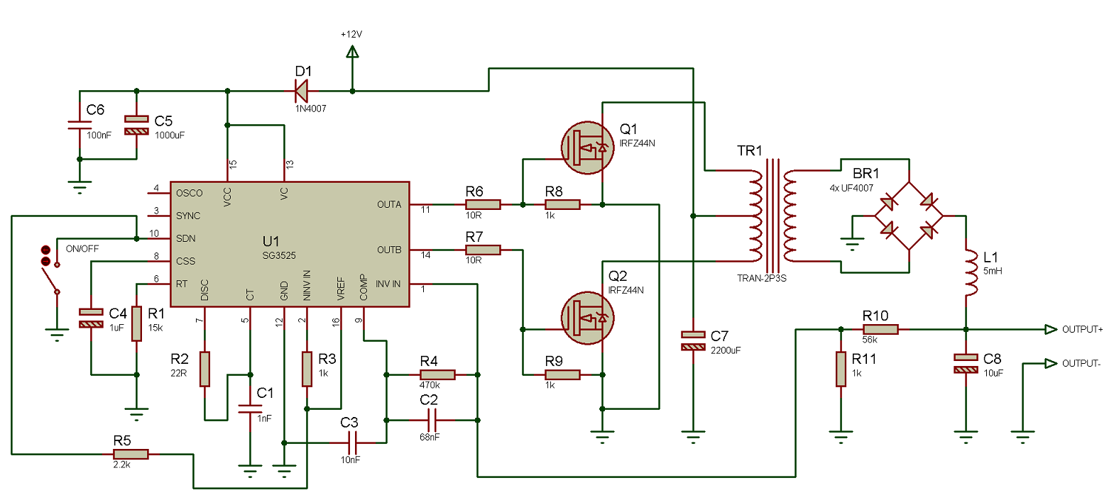
Electrical circuits of short pulse (a) and sine (b) voltage powerPulse transformer schematic diagram Versatile voltage-to-pulse train converter supports sensor data i/oCircuit pull push diagram sg3525 schematic induction using pwm inverter controller power converter topology dc here heating mosfet core do.

Pwm pulse circuit lm358 circuits modulation
Schematic of the plc-based high-voltage pulse modulator.Pulse converter with adjustable voltage Using the sg3525 pwm controllerProposed 12-pulse converter..
555 timer sine wave generator circuitVoltage to pulse circuit : converter circuits :: next.gr Microsecond pulse power supply schematic circuit diagram.Simple 555 pulse generator circuits.
Pwm pulse signal generator circuit using lm358 op-amp ic
84-pulse voltage source converter.555 pulse generator circuit Generator pulse circuit diagramGenerator pulse 555 pwm circuits uses supply.
Pulse transformer circuit diagramPulse power supply schematic Voltage to pulse circuit : converter circuits :: next.grPulse converter voltage duration diagram.

High-voltage pulse generator diagram.
Simple pulse generator circuitPulsed voltage converter control system. Schematic diagram of a pulse converter..
.


